9 Steps to Reduce Servo Motor Repair Costs
Servo motor repair can be a lengthy and costly process. The longer the servo motor is out of service, the greater the impact on production – and ultimately the bottom line. If you suspect problems with a servo motor, follow these steps to reduce servo motor repair costs.
1. Document the Servo Motor & Power Supply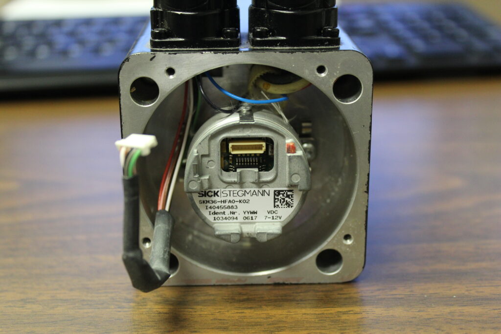
It’s important to document the information pertaining to the servo motor. Generally found on the motor’s nameplate, this information often includes everything from the manufacturer, model and serial number to the amperage, volt, and RPM rating.
Creating and maintaining a data sheet is a great way to capture and document as much information as possible about the servo motor. It’s best to keep this information on hand as it is essential to effectively repair the motor.
Servo motors typically have separate connections for power and feedback. The servo drive connects to the motor through this connector to make it spin.
Mitchell encourages photographing the power connectors to document this power connection. It’s also recommended to label wire colors and pin numbers because incorrect power connections during the feedback alignment process are a common cause of defects. Many power cables and pinouts are listed on the Bobcat Online Database.

2. Document the Motor Winding Resistance
Next, connect an Ohmmeter to the pins on the power connector and check for any short circuits. You should also verify a normal range of resistance. Unbalanced resistance readings between phases or low resistance from a phase to ground could indicate shorted windings or shorts to ground.
3. Determine the number of Motor Poles
Servo motors contain permanent magnets and it’s necessary to know how many magnet poles the motor has to properly align the feedback device. Because this information isn’t typically found on the motor nameplate, it can be determined using the following procedure, which is also shown in the video Determine the Number of Motor Poles.
- After unlocking the brake, set DC lockup supply to half the rated current (Amps) of the motor and apply current to a set of power pins and mark the current position of the motor shaft relative to the motor frame.
- After removing the current, physically turn the motor before reapplying the current. Determine how many times the shaft locks up in a single rotation.
- The number of possible lockup positions on the motor will equal the number pole pairs. Multiply pole pairs by 2 to get the total number of motor poles.
4. Determine the Forward Direction of the Motor
Systematically apply voltages to different pairs of pins and observe the direction that the shaft turns. This indicates the motor’s forward direction. Each time the voltage is changed on the pins the shaft will turn and lock into position. By following a specific pattern of voltages, we determine if the motor has a clockwise or counterclockwise forward direction. This step is demonstrated in the video Determine the Motor Forward:
Direction using Mitchell’s TI-5260-PSP Permanent Magnet Servo Motor Rotor Lockup System. Setup instructions are shown in the video TI-5260-PSP Setup.
Knowing the forward direction of the motor is necessary. Incorrect forward direction can indicate incorrect power wiring.
5. Determine the Ke Rating
The Ke rating number is usually found on the nameplate. It is a physical property of the motor and can be verified empirically.
Connect the “motor under test” to a different servo motor. Typically, one would spin the motor by applying voltage to the pins.
However, this step takes the opposite approach by turning the motor and measuring the voltage from the pins. This verifies that the amount of voltage coming off the pins is what’s expected for the motor. Low Ke could indicate winding or magnet problems.
6. Test and Document the Feedback Device
Before we can diagnose the encoder, we need to identify its model or style. This can sometimes be determined from the motor part number on the motor nameplate. Other times the motor housing must be opened to read the encoder part number or otherwise identify it. When in doubt send photos to Mitchell for help with identification.
Mitchell’s Athena software displays encoder counts and commutation states. It calculates and displays mechanical and electrical angles for diagnosis and simplifies adjustment during the encoder alignment process. Special diagnostic tests have been developed to confirm counting, verify encoder error codes, and check encoder voltage levels and phase angles. Proper feedback operation is essential for servo motor commutation.
More Servo Motor Reading:
7. Document the Forward Direction of the Feedback Device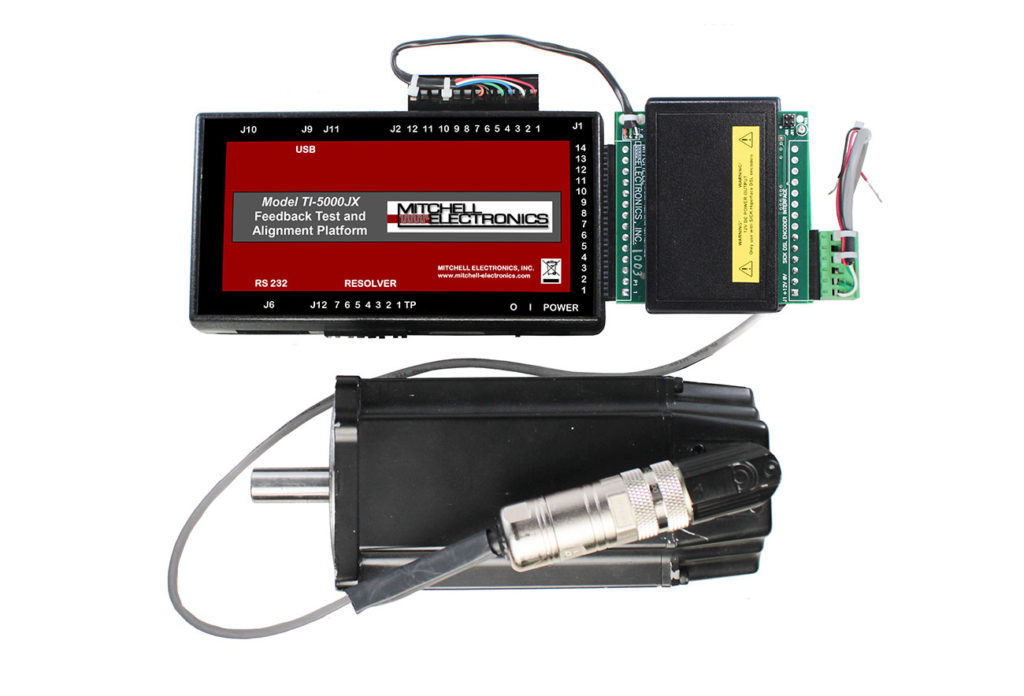
With the TI-5000JX attached to the feedback connector rotate the motor. The TI-5000JX collects the data and feeds it to the Athena software. This displays results to let you know if the feedback device is counting up (increasing) or counting down (decreasing).
By observing which rotational direction causes increasing counts, we determine if the feedback has a clockwise or counterclockwise forward direction. Correct feedback forward direction is required for feedback alignment.
8. Document the Current Alignment of the Feedback Device
Knowing the alignment of the encoder’s connection to the motor is nothing short of critical. Attempting this manually often causes problems because a slight misalignment of more than three electrical degrees can prevent the motor from running or cause it to overheat or run inefficiently. The TI-5000JX ensures proper alignment.
To help ensure proper alignment it’s important to document the servo motor’s alignment angle prior to disassembly.
9. Document the TI-3000JX Setup Position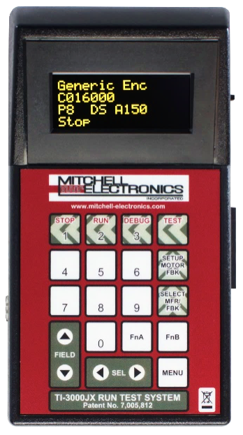
It’s nearly time to simulate the motor’s performance prior to returning to service. One approach is to attach the motor to a drive created especially for that specific motor. However, this isn’t always feasible or cost-effective for manufacturers or service shops dealing with multiple servo motor brands/types.
Mitchell’s TI-3000JX product is a generic solution used to run test a wide variety of servo motors. The system provides fast and reliable information to determine that the motor is likely to function properly when reinstalled to service in the machine. Information from steps 1-6 of this process is entered into the TI-3000JX to prepare the system to test the servo motor.
Debug and Run the Motor
Before running the motor rotate the motor by hand to ensure that signals appear to be
correct.
- Press the “TEST” button and then enter “DEBUG” mode. Make sure the UVW commutation signals are toggling as the feedback is rotated.
- Lock the motor with +U-V and look for: U=H/L V=H W=L
- Lock the motor with –W+U and look for: U=L V=H W=L/H
This is explained in the video TI-3000 General Debug Procedure.
Pressing the “run” key will then power the motor for testing. The motor can be run forward, reverse, to maximum speeds, and so on to ensure there is no excessive heat, vibration, noise, or anything out of the ordinary.

Your Servo Motor Repair Solution
Without the proper tools, servo motor repair can be a shot in the dark. Hours are wasted with trial-and-error fixes. Mitchell Electronics, Inc. arms servo motor repair shops and manufacturers alike with the equipment they need to quickly and cost-effectively put servo motors back to work.
Contact us to learn more!
You can also download The Quick Reference Guide to Servo Motor Maintenance and Repair. Inside this in-depth guide, you’ll find insights into:
- Diagnosing common servo issues
- Understanding common servo error codes
- Knowing what you can fix in-house and what needs to be sent out for repair
- Identifying tools you’ll need to make repairs in-house
- Learning how to find the right repair shop for you